


Pine fun - How low can we go...
One of the most pressing practical concerns of mobile phones is battery lifetime. We wondered, what can we expect from a Genode-based PinePhone? To find out, we took our custom SCP firmware as instrument to poke all the dials and knobs and we could find deep in the device.
We discovered early on that the key for sophisticated energy management lies in the so-called system control processor (SCP), which is a low-power companion CPU that complements the high-performance application processor for power-control tasks. This realization prompted us to create our custom SCP firmware, which we now took as an interactive instrument for experimentation and discovery.
For the following series of experiments, we used a Joulescope energy analyzer and powered the Pinephone exclusively via the power supply with the battery removed. The analysis was motivated by the following questions:
-
Which of the many potential power-saving opportunities have the most impact on the battery lifetime? With this question answered, we can focus our further efforts on the most promising optimization vectors.
-
What is the estimated battery lifetime under different kinds of load? This is important to realistically manage our expectations.
-
In anticipation of usage scenarios with prolonged standby times while staying receptive to incoming calls or SMS messages, how far can we reduce the power draw while still retaining software control over the device using our custom SCP firmware?
Baseline
To capture the base line of simple workloads without power considerations, we measured the current (A) and voltage (V) and thereby power (W) for the minimal-complexity custom Genode system scenarios.
|
|
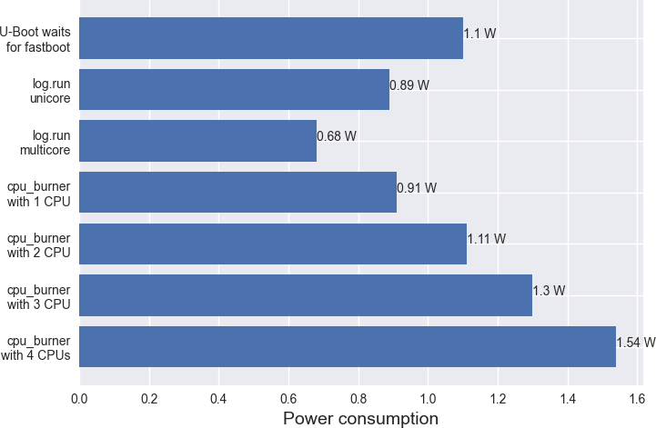
Baseline power consumption of low-complexity custom Genode system scenarios.
|
- U-Boot waits for fastboot
-
The boot loader actively polls the USB interface for the fastboot protocol, which is used for loading system images on the device. The high power draw is presumably caused by the active polling.
- log.run
-
The scenario consists of the base-hw microkernel, the init component, and a one-off test program that produces a few lines of log output. After the completion of the test program, the system is expected to reside in idle state. So the measured power draw of 0.89 W can be regarded as the lowest bound of power consumption of any Genode system with no special precautions about power management taken.
Interestingly, by activating multi-core support in the base-hw kernel - the A64 SoC has four ARM cores - the power draw decreases from 0.89 W to 0.68 W. This surprising effect is presumably caused by the CPU bootstrapping protocol as implemented by the ARM Trusted Firmware, which lets each CPU spin until activated. Once a CPU got activated and controlled by the base-hw kernel, it can go into the regular idle mode when no thread is executing.
As the bottom line of this experiment, the lowest bound of a power-unaware Genode system scenario on the Pinephone is 0.68 W.
- cpu_burner.run
-
The CPU burner test is the opposite of the log test with respect to CPU load. It puts a configurable number of CPUs under 100% computational load with no idle time. Depending on the number of 100% active CPUs we observed the power draw to go from 0.68 W (all CPUs idle) up to 1.54 W (four CPUs busy).
The CPU load has a significant effect. A fully CPU-saturated system consumes more than twice amount of energy compared to an idle system.
The basic tests above stressed merely the CPU but left peripheral devices largely untouched. According to common wisdom, the display is the most power hungry part of a mobile phone.
Display
To analyse this claim, we used a custom Genode test scenario that repeatedly starts and removes the framebuffer driver, which we ported from the Linux kernel. The scenario shows the unskewed effects of the display because it touches no other peripheral.
With the display enabled but CPUs being idle, the scenario draws 1.6 W using the default brightness. Interestingly, the power draw of the system did nowhere near decrease to the 0.68 W idle power draw once the driver gets removed again. With the driver removed, the system continued to consume 1.1 W. Investigating this effect, we found two GPIO pins - controlled by the display driver - that were left in output state once the driver was removed. By reverting their output states to zero, the power draw decreased to 0.78 W. This is arguably still larger than the idle draw of 0.68 W.
Backlight
The display backlight is controlled by a single PWM (pulse-width modulation) digital output device. Both the frequency and active phase can be configured by software.
| PWM setting | Observable effect | Power |
|---|---|---|
| 0% active phase | no visible picture | 1.47 W |
| 25% active phase | default brightness | 1.6 W |
| 100% active phase | maximum brightness | 2.03 W |
Table 1: Backlight power draw with different PWM settings
As one experiment, we gradually increased the active phase in 40 steps from 0% to 100% of the total duration (1280), which produced an almost linear characteristic curve. The values in the table above show that the display brightness influences the power draw by up to 0.55 W, which is substantial but notably less than the power draw induced by high CPU load. The default brightness as configured by the Linux framebuffer driver is apparently a very sensible choice as it yields a clearly visible picture while drawing only 0.13 W more than the lowest (totally invisible) setting. We also experimented with varying the total PWM phase length but to no measurable effect. The main takeaway is that the removal of the entire framebuffer driver is significantly more effectful than the mere dimming of the screen.
Touchscreen
Similar to our isolated display test, we conducted an isolated touchscreen test with no other driver present. To our satisfaction, we found the touchscreen driver to produce a rather marginal power increase of 0.07 W over the idle system. However, while touching the device, the power draw increased by another 0.2 W. Even though we find the effect surprisingly steep, it is hardly a worthwhile optimization vector.
How low can we possibly go?
On our quest regarding the third question about prolonged standby times, we conducted the following series of experiments. The stated goal was to disable as much device functionality as possible while retaining principle control over the platform. In order to manipulate all power outputs of the AXP803 power management chip (PMIC), we had to implement driver code in Forth for accessing this chip from the SCP over a two-wire bus named RSB.
Switching off individual voltages via the AXP803 PMIC
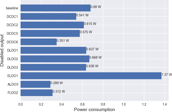
In the first experiment, we used the PMIC's output-control registers to directly control the physical power outputs as supplied to the various parts of the Pinephone including the A64 SoC and peripherals. Naturally, some of the outputs are fundamentally needed for powering the SCP itself and its ability to interact with the outside world (via UART or LED). When touching those, the SCP goes visibly dead. The following table summarizes the effects when pulling each power output individually. As the baseline for this test, we ran the log.run scenario with all ARM CPUs idle, which has a baseline power draw of 0.68 W.
| Output | Default | Effect | Power |
|---|---|---|---|
| DCDC1 | on | SCP silent | 0.541 W |
| DCDC2 | on | SCP alive | 0.615 W |
| DCDC3 | on | no change | |
| DCDC4 | off | ||
| DCDC5 | on | SCP alive | 0.575 W |
| DCDC6 | on | SCP dead | 0.351 W |
| DC1SW | on | no change | |
| DLDO1 | on | SCP alive | 0.637 W |
| DLDO2 | on | SCP alive | 0.668 W |
| DLDO3 | on | SCP alive | 0.636 W |
| DLDO4 | on | no change | |
| ELDO1 | on | SCP alive | 1.37 W (increase!) |
| ELDO2 | off | ||
| ELDO3 | off | ||
| ALDO3 | on | SCP dead | 0.289 W |
| ALDO2 | on | no change | |
| ALDO1 | off | ||
| FLDO2 | on | SCP dead | 0.312 W |
| FLDO1 | on | no change |
Table 2: Effects of disabling individual PMIC power outputs.
|
|
Change of power draw with individual outputs disabled.
|
The most interesting power outputs for our purpose are the ones depicted above, especially those where the SCP stays alive while the power consumption visibly decreases, which are DCDC2, DCDC5, DLDO1, DLDO2, and DLDO3. The latter are apparently non-critical for the SCP. Interestingly, the disabling of ELDO1 increased the power draw. It is probably best to not poke this one too much with a stick.
|
|
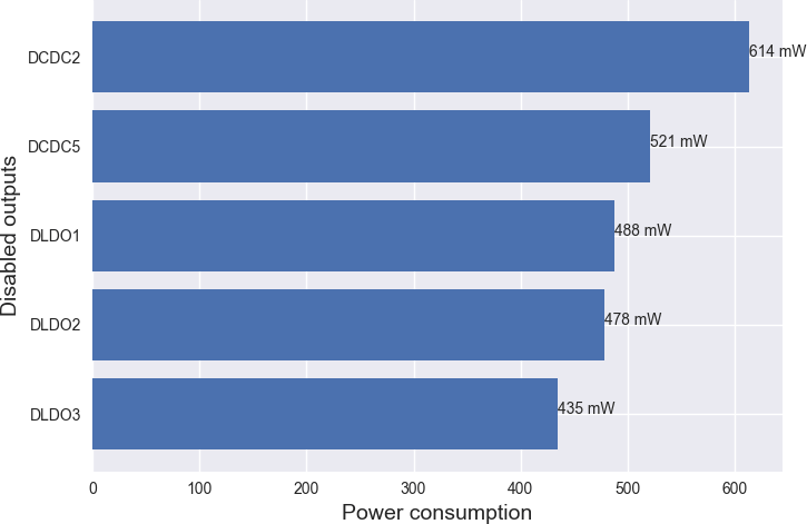
Effects of successively disabling non-critical power outputs.
|
By successively disabling all non-critical power outputs, we can see the cumulative effects of the individual outputs on the overall power draw in the figure above. The power outputs apparently contribute independently from each other. With all non-critical outputs disabled, the power consumption dropped by about 40%.
To rule out the possibility of declaring the SCP dead while merely disabling its I/O channels to the outside world, we refined the experiment by disabling and re-enabling individual power outputs after a delay of a few hundred milliseconds. To our delight, we found that DCDC1 has precisely this effect. After switching off DCDC1, the SCP became silent. But it successfully re-enabled DCDC1 and thereby regained its I/O capabilities. While disabling DCDC1, the power draw dropped from 0.435 W further down to 0.278 W.
PLLs, clock, and reset gatings
After toggling the lowest-level power outputs at the PMIC at coarse granularity, we turned our attention to the fine-granular power control opportunities offered by the A64's clock and reset control unit (CCU).
However, there exist a staggering amount of knobs to try, most of which are not explained in the public documentation. With our concrete goal of preserving the liveliness of the SCP in mind, we took a sledge-hammer approach to find the bits of most interest.
We tweaked our custom SCP firmware to sequentially disable all bits of all CCU registers, giving us a life sign on the serial console, and proceed with the next register if still alive. Once we hit a deadly register, we changed the code to deliberately step around it during the next try. While watching the SCP marching on with disabling all CCU bits, we kept an eye on the Joulescope energy analyzer to correlate effects on the power consumption with CCU register ranges.
We found that there are apparently only a few really "deadly" registers, namely PLL_PERIPH0, APB2_CFG_REG (UART baudrate), BUS_CLK_GATING_REG3 (gates UART), and BUS_SOFT_RST_REG4 (resets UART). With all other CCU bits cleared, the total power draw went down from 0.435 W to 0.377 W with DCDC1 enabled, respectively from 0.278 W to 0.067 W once DCDC1 was temporarily disabled.
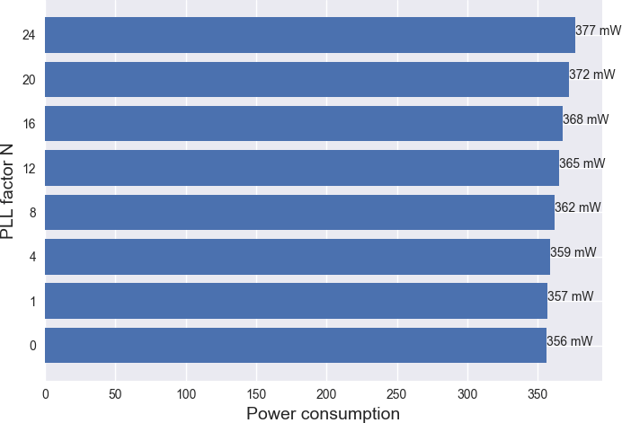
At this point, our attention was naturally attracted by the four "deadly" registers. And in fact, the PLL_PERIPH0 control register turned out to be another interesting optimization vector. It apparently controls the frequency of a PLL (phase locked loop) supplied to various peripheral device parts of the SoC. However, while scaling down the frequency, we found the SCP unaffected by its configuration as long as it stayed enabled. The figure below shows the effect of successively reducing the PLL scaling factor N from 24 (default) to 0. As baseline, all non-critical PMIC power outputs except for DCDC1 were disabled and all non-critical CCU registers were cleared.
|
|
Effect of scaling the frequency defined in PLL_PERIPH0.
|
Even though the values do not look spectacular, the toggling of DCDC1 at this point had an impressive effect. It reduced the total power draw to only 0.049 W.
Voltage scaling and further acts of desperation
The PMIC can not only be used to toggle the various power supplies but also to tweak their voltages. Our attention was first drawn to the DCDC1 output because we observed the massive effect of disabling it while SCP stays alive. It is merely deprived of communicating with outside world while DCDC1 is disabled. We asked ourselves how far can we reduce DCDC1 until the SCP communication over UART breaks? By default, DCDC1 is set to 3.3 V. To our surprise, we can reduce the value in the DCDC1 voltage-control register from default value 0x11 down to 0 while the SCP's UART communication stays in tact, yielding a power draw of 0.074 W. In this state, we can still interactively execute Forth commands on the SCP! The effects of reducing ALDO3 (to 0x9) and DCDC6 (to 0x18) were less dramatic but still noticeable.
While reviewing the PIO registers, we noticed that reconfiguring the GPIO pins for the SD-card to disabled mode saves us another 0.05 W.
When combining all these measures, we can get as low as 0.021 W while still maintaining principle control over the device.
According to the PinePhone's battery specification, the battery has a rated capacity of 10.64 Wh. Therefore, the low-power state could theoretically be held for up to 20 days, which we find rather impressive. However, don't let this result fool you. First, it does not account for the power draw of the modem in sleep state. Second, disabling DCDC1 may not be viable for the purpose of interacting with the modem. Third, we entered an operational state where the DRAM is switched off. So the only way to reasonably respond to an external event like an incoming call would be a cold boot of the application processor, which brings the problem of boot times onto our table. Let's save that topic for later.
That said, thanks to our series of experiments, we gained a clear picture of the various contributors to the overall power consumption and the power-scaling capabilities of the hardware. We found impressive room for creativity that calls for exploration.