


Pine fun - One Platform driver to rule them all
In the previous article we exercised direct-device access from user-level components. In Genode systems beyond such toy scenarios, however, it would be irresponsible to follow the path of allowing arbitrary drivers to access any device willy-nilly. Our call for discipline and rigidity is answered by the (rising drum roll) platform driver.
Let's recap the scenario of the previous article.
|
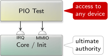
Our user-level test program created connections to core's services for accessing memory-mapped I/O registers and receiving notifications for device interrupts. The choice of physical register addresses and the GIC interrupt number was up to the test program. So in principle, our program could access any part of the platform by just requesting it. Hence, the mere fact that the driver code has the form of a regular user-level component does not buy us a security gain per se. To benefit from Genode's architecture, we need to rigidly limit the reach of each individual driver to the smallest-possible set of device resources.
Remember, even though we want to use drivers, we distrust them. Consequently, besides enforcing access control, we generally don't want to expose system-global information to such untrusted components, asking questions like: Does a driver even need to know the physical address of a memory-mapped I/O register? Does it need to know the GIC interrupt number of the device it is driving? The perhaps surprising answer is that - no! - many drivers can happily do their job without any knowledge about these technicalities. All a driver needs to know is how to speak to a device of a certain type, not where a particular instance of a device is located and how it is wired up. This principled approach leads to a clear-cut separation of driver logic from parametrization.
Platform driver
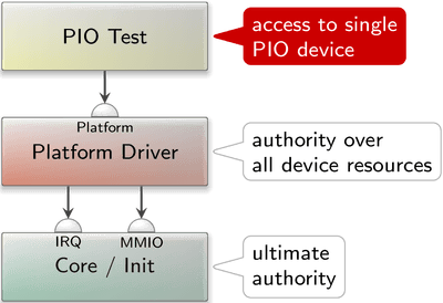
To separate the concerns of parametrization and access control from the device drivers, Genode employs the so-called platform driver as a level of indirection between core's services and the individual drivers. The platform driver has a global view over all device resources and follows a configured policy to partition those resources between its clients. Each session to the platform service can comprise potentially multiple devices, depending on the configured policy.
|
To integrate the notion the platform driver into our existing scenario of accessing general-purpose I/O pins via a to-be-developed PIO device driver, it is best to first sketch a run script that mirrors the picture above. We have to find a suitable name and location within our source tree for our designated driver component.
The naming of driver components within Genode follows the pattern
<device-or-platform>_<driver-type>_drv
For example, the imx8_fb_drv is a framebuffer (fb) driver for the i.MX8 SoC. In our case of a PIO driver for the Allwinner A64 SoC, the name a64_pio_drv is a sensible choice.
Even though there is no strict convention of the directory where a driver is located, drivers usually reside in a subdirectory of src/drivers/ that corresponds to the primary purpose of the driver. E.g., framebuffer drivers are located at src/drivers/framebuffer/. Our designated driver drives GPIO pins. So I settled on placing it at src/driver/pin/a64/ within the genode-allwinner repository. With the complicated naming-things-topics behind us, let's turn our attention to the run script, appropriately named a64_pio_drv.run.
-
Building the components including the platform driver along with our new custom driver.
build { core init drivers/platform drivers/pin/a64 } -
Creating a boot directory with the configuration of the init component.
 create_boot_directory

 install_config {
   <config>
     <parent-provides>
       <service name="LOG"/>
       <service name="PD"/>
       <service name="CPU"/>
       <service name="ROM"/>
       <service name="IO_MEM"/>
       <service name="IRQ"/>
     </parent-provides>

     <default caps="100"/>
     ...

   </config>
 }
At this time the scenario consists of only two components, namely the platform driver and our PIO driver. The <start> node for the platform driver is particularly interesting.
 <start name="platform_drv">
   <resource name="RAM" quantum="1M"/>
   <provides> <service name="Platform"/> </provides>
   <route> <any-service> <parent/> </any-service> </route>
   <config devices_rom="config">
     <device name="pio">
       <io_mem address="0x1c20800" size="0x400"/>
       <irq number="43"/>
     </device>
     <policy label="a64_pio_drv -> ">
       <device name="pio"/>
     </policy>
   </config>
 </start>
The routing rule states that the platform driver is permitted to open arbitrary sessions to core, including IRQ and IO_MEM. There are no restrictions.
The <provides> declaration states that this component offers a "Platform" service.
The <config> node tells the platform driver to determine the information about the present devices from the ROM module labeled "config", which allows us to specify both the device information and the policy inside the same
<config> node. Without the devices_rom="config" attribute, the platform driver would request a "devices" ROM session instead. We declare the existence of a single "pio" device that features one memory-mapped I/O range and the GIC interrupt 43. You may recall those values from the previous article.
The <config> node also tells the platform driver about the access-control policy applied to clients that connect to the platform service. In the case at hand, we dictate that a client labeled as "a64_pio_drv -> " gets access to the "pio" device. You may wonder about the trailing -> part of the label. The part before the arrow is hard-wired by the parent of the a64_pio_drv and thereby reflects the identity of the client in a way that cannot be forged by the client. The part after the arrow is controlled by the client. The client can use this part to provide hints about the purpose of the session. So a client that creates multiple sessions to the same server can express the intention behind those sessions. In our case, this client-controlled part remains unused.
The <start> node for our designated PIO driver looks as follows.
 <start name="a64_pio_drv">
   <resource name="RAM" quantum="1M"/>
   <route>
     <service name="ROM"> <parent/> </service>
     <service name="CPU"> <parent/> </service>
     <service name="PD">  <parent/> </service>
     <service name="LOG"> <parent/> </service>
     <service name="Platform"> <child name="platform_drv"/> </service>
   </route>
   <config/>
 </start>
Let me bring the <route> node to your attention. In contrast to the wildcard rule <any-service> used for the platform driver, the rules for the PIO driver state explicit permissions. From these rules, we can immediately infer the potential reach of the component.
The driver is permitted to connect to the platform driver. That's what we want. It is also able to use core's ROM, CPU, PD, and LOG services, which provide the fundamental ingredients for executing the program.
Most importantly, no other service is reachable. In particular, the direct use of core's IRQ and IO_MEM is out of question. The only way to access a device is the platform driver that imposes its policy.
-
Building the boot image containing the ELF binaries for the components and executing the scenario.
 build_boot_image { core ld.lib.so init platform_drv a64_pio_drv }

 run_genode_until forever
For reference you can find a commit for this step here.
To exercise the interplay between the designated PIO driver with the platform driver, it is a good idea to transplant the test/pin_state program of the previous article from the use of core's services to the use of the platform driver. The following snippet highlights the important changes.
 #include <platform_session/device.h>
 ...

 struct Pio_driver::Main
 {
    Env &_env;

    Platform::Connection _platform { _env };

    Platform::Device _device { _platform };

    struct Pio : Platform::Device::Mmio
    {
       struct Pb_cfg0 : Register<0x24, 32>
       {
          ...
       };

       ...

       Pio(Platform::Device &device) : Mmio(device)
       {
          ...
       }
    };
    ...
    Pio _pio { _device };
    ...
 };
-
The API for using the platform driver becomes available via
#include <platform_session/device.h>
-
A session to the platform service is established by creating an instance of a Platform::Connection passing the Genode environment as argument.
Platform::Connection _platform { _env };By passing the _env, we explicitly give our consent that the Platform::Connection can have global side effects such as the communication with the outside world.
-
Access to one particular device of the platform session can be obtained by creating an instance of a Platform::Device.
Platform::Device _device { _platform };When called with only the Platform::Connection as argument, the device refers to the first - and in our case only - device of the platform session. In cases where multiple devices appear grouped in one platform session, a second argument allows for the selection of the device.
-
The memory-mapped registers of the PIO device are represented by a custom Pio type that inherits the Platform::Device::Mmio type.
struct Pio : Platform::Device::Mmio
The constructor takes a Platform::Device and an optional index as arguments.
Pio _pio { _device };If no index is provided, it refers to the first <io_mem> resources as declared in the platform-driver's configuration.
-
Thanks to the inherited Platform::Device::Mmio type, the individual registers can be accessed in the same way as we did in the previous article.
Note that in contrast to the previous examples, the code is void of physical addresses. Now, those addresses are the business of the platform driver only.
Session interfaces for accessing pins
We ultimately want to allow multiple programs to interact with different GPIO pins. So our PIO driver must evolve into a server component that allows clients to interact with pins. Analogously to how the platform driver safeguards the access to device resources by different - mutually distrusting - device drivers, the PIO driver's job will be the safeguarding of GPIO pins.
Traditionally, Genode features the "Gpio" session interface for this purpose. This interface allows a client to access an individual pin. Once assigned to a pin, the session grants the client the full responsibility for the pin. In particular the direction of the I/O pin is laid into the hands of the client. We later realized that the wiring and thereby the direction of a pin is ultimately a board-level decision. Wrongly operating an input pin in output mode can easily result in a short-circuit. Therefore, the client of an individual pin should better not be burdened with the responsibility to control the pin direction or pull resistors. To address this concern, it is best to split the roles of GPIO pins into clear-cut session interfaces. Those roles are:
-
The sensing of the state of a GPIO pin, e.g., detecting whether a button is pressed or not: operating a pin as an input signal. This role is now covered by the "Pin_state" session interface with the single RPC function
bool state() const;
By calling this function, the client can request the state of the pin. That's it.
-
Controlling the signal level of a pin: operating a pin as an output signal. This role is now addressed by the "Pin_control" session interface that provides an interface of only one rather unsurprising RPC function
void state(bool);
-
Receiving a notification of a change of the signal level of a GPIO pin: operating a pin as an interrupt source. This role can be represented by Genode's existing IRQ session interface - the same interface as provided by Genode's core for GIC interrupts.
PIO device driver
The A64 PIO driver implements the three session interfaces outlined above. It resides at src/drivers/pin/a64 within the genode-allwinner repository. The accompanied README covers the details about its use and configuration.
Similar to how the platform-driver configuration declares device resources like IRQs and memory-mapped I/O regions, the PIO driver's configuration declares pins.
 <config>
   <out name="led"    bank="B" index="2" default="on"/>
   <in  name="button" bank="H" index="8" pull="up" irq="edges"/>
   ...
 </config>
Here we see the declaration of an output pin named "led" and an input pin "button". The bank and index denote the physical location of the pin at the SoC. Further pin parameters are expressed as attributes. For example, in the absence of a "Pin_control" client for the "led", the led is set to state "on" according to the default attribute.
Since the A64 PIO device subsumes GPIO functionality as well as I/O MUX functionality, the driver also offers the selection of pin functions beyond <in> and <out>.
For reference, the commit for the driver implementation can be found here. A few technical tidbits and caveats I encountered during its development are worth sharing:
- Device-register interaction
-
The actual interplay of the driver with the hardware registers is completely covered by the code found in pio.h. Genode's Mmio framework API makes this code strikingly simple, almost self-describing. There is no manual bit fiddling to be found, thanks to the wonderful Register_array.
- Code organization
-
I deliberately split the code into a boring and an interesting part.
The boring part models the SoC-specific terminology as a bunch of corresponding C++ types. In types.h one can find types for any term we deal with - however boring it is. Most of these types have a local Value type that is as rigid as possible. E.g., the Pull type contains an enum with the values DISABLE, UP, and DOWN as the Value type. The degrees of freedom mirror the information found in the SoC manual. Each type is equipped with a class function from_xml that encodes the knowledge of how values of the type relate to XML representation. Some of the types go as far as deliberately disabling any means to construct instances of the type without using from_xml by deleting the default constructor. This way, program-global invariants of the type can be enforced at a single place. The boring code makes up the biggest part of the driver. This is good because with "boring" I mean simple and easy to assess for correctness.
The interesting part lives in the main.cc file where all the strings are coming together.
- Stumbling blocks
-
Quite a bit of time went wasted because of silly mistakes of mine.
Sometimes I went too hastily over the SoC documentation without double checking. In particular, I allowed myself be become misled by a table in the SoC documentation at page 376 where I wrongly identified patterns that do not exist. In one part of the table, the symbol n seemingly refers to a zero-indexed value corresponding to GPIO banks in alphabetic order. Some lines below (at the Pn_INT_*) definitions, the n refers only to a few banks, namely B, G, H. I wrongly assumed the same linearity of register layouts to apply for both parts of the table. In reality, n must just be read as a shorthand of "some value". Note to myself: Double check my assumptions each time I'm overconfident that I got it.
Because of my prolonged intimacy with pin 2 at bank B, I lost sight of the other banks, in particular the fact that each bank is wired up with a distinct GIC interrupt. Once I tried to receive interrupts for pin 8 at bank H, I first struggled to get the interrupt mechanism to work, until I realized that bank H interrupts end up at GIC IRQ 53, not 43. In fact, the "pio" device in the platform driver configuration now looks like this:
 <device name="pio">
   <io_mem address="0x1c20800" size="0x400"/>
   <irq number="43"/> <!-- Port B -->
   <irq number="49"/> <!-- Port G -->
   <irq number="53"/> <!-- Port H -->
 </device>
- Implementation of dynamic re-configurability
-
For maintaining the internal data model of the pin-state configuration, the driver employs Genode's List_model utility. By using this utility, the creation and updating of such a data model from XML data becomes very simple. It comes down to providing hook functions for creating, destroying, matching, and updating model items.
It is worth noting that the driver configuration is not static but it can be dynamically adjusted during runtime. So in principle, we can attain a blinking LED by the sole means of re-configuring the driver.
Dynamic configuration testing
Wait what!?
If blinking an LED by reconfiguring the PIO driver sounds as irresistible to you as to me, follow me for a moment.
For test-driving the dynamic configuration handling of components like the A64 PIO driver, there exists a handy utility component called dynamic_rom, which provides a ROM service that feeds the client with different version of ROM content over time. Here is how a <start> node of a dynamic_rom server looks like.
 <start name="dynamic_rom">
   <resource name="RAM" quantum="1M"/>
   <provides> <service name="ROM"/> </provides>
   <route>
     <service name="Timer"> <child name="timer"/> </service>
     <any-service> <parent/> </any-service>
   </route>
   <config>
     <rom name="config">
       <inline description="LED off">
         <config>
           <out name="led" bank="B" index="2" default="off"/>
         </config>
       </inline>
       <sleep milliseconds="1000"/>
       <inline description="LED on">
         <config>
           <out name="led" bank="B" index="2" default="on"/>
         </config>
       </inline>
       <sleep milliseconds="1000"/>
     </rom>
   </config>
 </start>
The <rom> node within its configuration defines a PIO <config>. After 1 second, the <config> is replaced with a new version where the default attribute of the <out> pin is toggled. After one more second, the first <config> becomes active again.
The remaining piece of the puzzle is feeding the ROM provided by the dynamic_rom server as config ROM to the a64_pio_drv driver. This can be achieved by the following routing rule in the <start> node of the a64_pio_drv component.
 <start name="a64_pio_drv">
   ...
   <route>
     <service name="ROM" label="config">
       <child name="dynamic_rom"/> </service>
     ...
   </route>
 </start>
By wiring up the driver configuration to the dynamic_rom we can see the LED happily blinking even without any "Pio_control" client present.
The dynamic_rom server is handy utility in many testing situations. Besides issuing time-triggered configuration updates, it can be used to mock system-state changes that are normally driven by real components or sensory input that is difficult to fabricate manually.
Cascaded authorities
Similarly to the configuration concept of the platform driver, the pin-declarations of the PIO driver configuration are followed by a policy part of the configuration that associates clients with pins.
 <config>
   ...
   <policy label_prefix="pin_event ->" pin="button"/>
   <policy label_prefix="pin_pulse ->" pin="led"/>
 </config>
This configuration assigns the "led" pin to the program "pin_pulse", and the "button" to the program "pin_event". Note that - like the pin declarations - these assignments can be dynamically changed by the means of configuration updates.
The "pin_pulse" component uses the "Pin_control" session to drive the digital signal of an LED with a pulse-width-modulated pattern. Effectively, the program toggles the LED 200 times per second while adjusting the relation of the durations of the low and high signal levels over time. The result is a nice breathing effect.
The "pin_event" component watches the state of a pin using a combination of an IRQ session and a "Pin_state" session. Each time when the signal changes, an IRQ is triggered, which prompts the component to obtain the pin state by calling Pin_state::state.
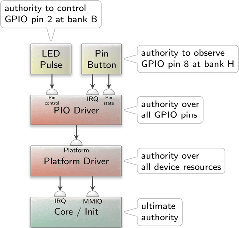
The component composition of the scenario looks as follows.
|
The higher up we get, the less influential the components become. Whereas the kernel has ultimate authority over everything, the reach of the pin-pulse component is limited to the control of the output signal of a single GPIO pin only.
As indicated by the coloring of the components, policy and mechanisms are nicely separated. The pin-pulse component does not even know which pin it is driving. It merely contains the logic needed to modulate the PWM pattern on a digital output signal. At the bottom end of the picture, the core / kernel component does have no interpretation of physical device addresses or IRQ numbers. It is indifferent regarding GIC IRQ number 43 and free from policy. The policy is encapsulated in the forms of the platform and PIO driver components, each respectively applying a policy at a useful level of abstraction.
Integrated test scenario
The final version of the a64_pio_drv.run script contains the combinations of the various fragments discussed above. It test-drives the dynamic re-configurability of the PIO driver along with the "Pin_state", "Pin_control", and IRQ session interfaces.
For the test of the GPIO input, I selected pin 8 of bank H. This pin is accessible at the Euler connector at pin 10 of the Pine-A64-LTS board. The board has a button labeled "power" just besides the reset button. Although this "power" button is connected to the AXP803 power management chip, it doesn't appear to have any effect when pressed while the board is on. According to the board schematics, the button happens to be also wired to pin 5 of the smaller 10-pin Euler header. I figured that I can thereby feed the button state to the GPIO pin H8 be connecting pin 5 of the small Euler header with pin 10 of the large Euler header. The signal is active-low, which can be explained by the schematics that shows that the button pulls the PWR_ON signal to ground when pressed. Long story short, with this wiring in place, the power button can be observed via GPIO H8. The GPIO pin B2 can be connected to an LED as we did for the test/pin_control example described in the previous article.