


Pine fun - Telephony (Roger, Roger?)
In this article we will describe how we enabled basic telephony support on the PinePhone.
LTE Modem
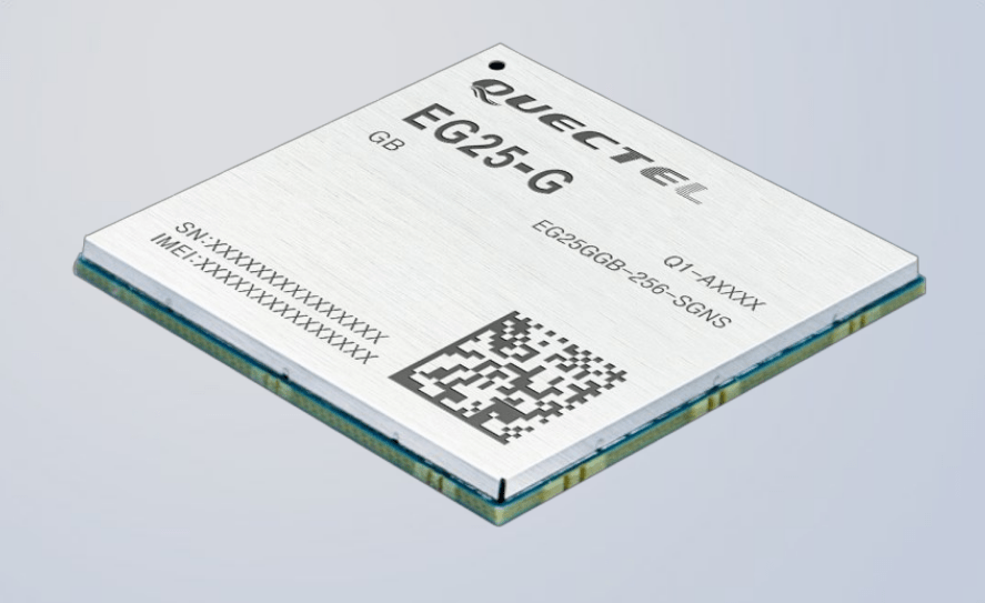
The PinePhone ships with a stock Quectel EG-25-G LTE capable modem designed for machine to machine communication. Inherently, the modem is a system on a chip (SoC) in itself with its own CPU core (Qualcomm MDM9207), RAM (256MB), and flash memory (256MB). It features next to LTE/UMTS/GSM, audio codecs, audio playback, GPS, and Bluetooth support.
|
|
Quectel EG25-G
|
Firmware
The firmware is essentially a custom Linux system that PinePhone's Allwinner A64 SoC can interact with through UART, USB, and PCM interfaces4. A speciality of the Quectel modem is the support to flash custom firmware into the modem. With this feature, it is possible to execute well-known trusted firmware instead of opaque binary blobs on the modem. An example of such a firmware is the PinePhone Modem SDK as provided by Biktorgj. The firmware offers better power-management support because it can scale the CPU frequency down to 100MHz (stock firmware is 400MHz) during sleep. Additionally it offers some features like non-persistent storage, time synchronization from carrier to user space, as well as zero binary blobs unlike the stock firmware. The non-persistent storage is especially interesting because the stock firmware may corrupt the flash memory - and thereby the whole SoC - if not shutdown correctly. This could happen on a crash or in case of battery failure. A downside of the custom firmware is that it is not feature complete, might be unstable, and in the worst case can even brick the modem. For these reasons, we decided to stay with the stock firmware for our telephony experiments.
UART and USB interfaces
Traditionally, modems are accessed through serial UART interfaces using the AT command set This feature is still provided by all modern modems. It can be used for placing and receiving calls, sending and receiving SMS, managing the SIM card, phone book, selecting carriers, managing audio, or GPS. For a complete list of the AT commands supported by the Quectel EG25-G, please refer to the official manual.
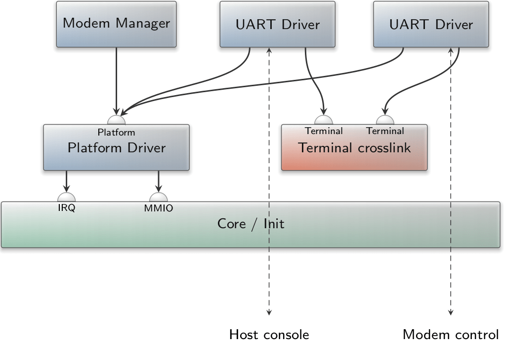
The UART of the Quectel modem is connected to UART3 on the Allwinner SoC, which is a standard 16550 UART as used by normal PCs since 1987. A driver for this UART was already present in Genode but only for the output (TX) case, since it was solely used for logging to the serial port. Because for each AT command sent via the UART to the modem a response is generated, we had to extend Genode's UART driver with receive (RX) support. This way, any terminal emulator (e.g., minicom, picocom, screen) can connect to the UART, send AT commands, and receive responses. Unfortunately this will only work if the modem is powered on.
The USB interfaces are used for data connections (2G/3G/4G) because UARTs are not fast enough (i.e., 115200 baud) to handle the data rates - up to 300 MBit/s - supported by modern standards. In this case, the modem exposes a USB network interface in order to send and receive data plus an additional control channel to configure the connection. For a basic description on the workings of data connections, please refer to our LTE modem support for Genode article. Because we were primarily interested in telephony at this point, we did not enable the USB part nor the Allwinner SoC connections of the modem - which in turn conserves power - and handled telephony through the UART interface using AT commands.
Modem startup
As with most SoCs, the modem is not powered during PinePhone's boot process. This requires manual power-on/off handling by Genode. Important to know is that the modem is powered by the battery directly and cannot be started with just the USB charger plugged in. The reason for this is that the power consumption of the modem can be anywhere from a 2 mA (sleep) up to 700 mA (LTE data) and may vary abruptly, which does not go well with power supplies but can be handled by a battery.
The modem is connected through various input/output pins (GPIO) to the Allwinner SoC through the Port controller. Without going into too much detail, there is one pin that enables the power supply from the battery to the modem. Once the power supply is ready, the modem can be powered on through a PWRKEY pin. This pin must be pulled down for at least 500 ms, which will initiate the modem's boot process that can take up to 30 seconds. In order to determine if the modem is powered on, another pin (status) can be observed. When the pin goes low, the modem has finished booting. For Genode, we have implemented this behavior in a small component called modem manager.
|
|
Experimental modem setup on Genode's PinePhone.
|
Basic telephony scenario
With the modem powered, we can connect to the UART of the modem using a terminal emulator and should see:
> RDY
This means we can now enter AT commands, the simplest would be:
 AT
 > OK
Enter the PIN for the SIM card:
 AT+CPIN=1234
 > OK
Check the connection status:
 AT+CREG?
 > CGREG: 0,1
 > OK
This means the modem is connected to the home network. Issue a call:
 ATD03513231421424;
 > OK
Hang up:
 ATH
 > OK
If one sees a
> RING
one can accept the call by
> ATA
The recommended way to shutdown the modem before the PinePhone is powered off is
AT+QPOWD
With these simple commands, we achieved basic telephony support at an extremely low complexity on the Genode side. The only noteworthy drawback is that no one can hear you and you can hear no one because audio has not been setup yet. We will look into this next.
Audio codec
The Allwinner SoC audio codec is split into two parts. First, an analog part for microphones, speakers, and headsets. And second, a digital part where the SoC itself, the modem, and the Bluetooth interfaces are connected to. As expected, analog-to-digital converters (ADC) and digital-to-analog converters (DAC) bridge both the analog and digital worlds for recording and playback.
|
|
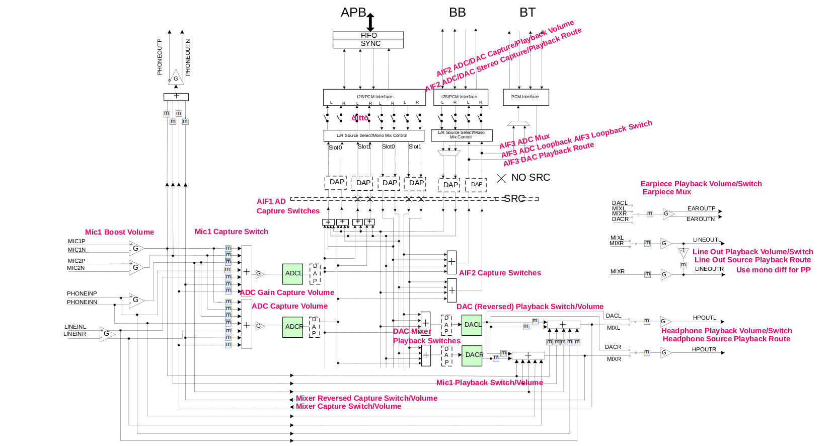
Figure 3: Allwinner A64 audio codec
|
Figure 3 shows the actual interconnection between all of the components involved, with some very helpful annotations from xnux.eu. At the top, three different AIFs (audio interface) are displayed. AIF1 leads to the APB bus, which in turn connects to the Allwinner SoC. AIF2 connects to the BB (base band), which is the Quectel modem whereas AIF3 connects to Bluetooth that is not of interest for this line of work. The green boxes ADCL/R and DACL/R are the connection to the analog part of the codec, where the recording and playback devices are connected to.
The whole scenario depicted in Figure 3 leads to the assumption that the microphone of the PinePhone and the earpiece/speaker can be routed through simple configuration to and from the modem without the actual involvement of the SoC (AIF1). AIF1 exists for playback sounds/music, record audio, and handle data connections like video conferencing where data packets need to be sent to the speaker while microphone inputs need to be transferred to the modem. AIF1 would also require an actual sound driver within Genode. Note that the modem implements this driver locally for itself because it has its own operating system.
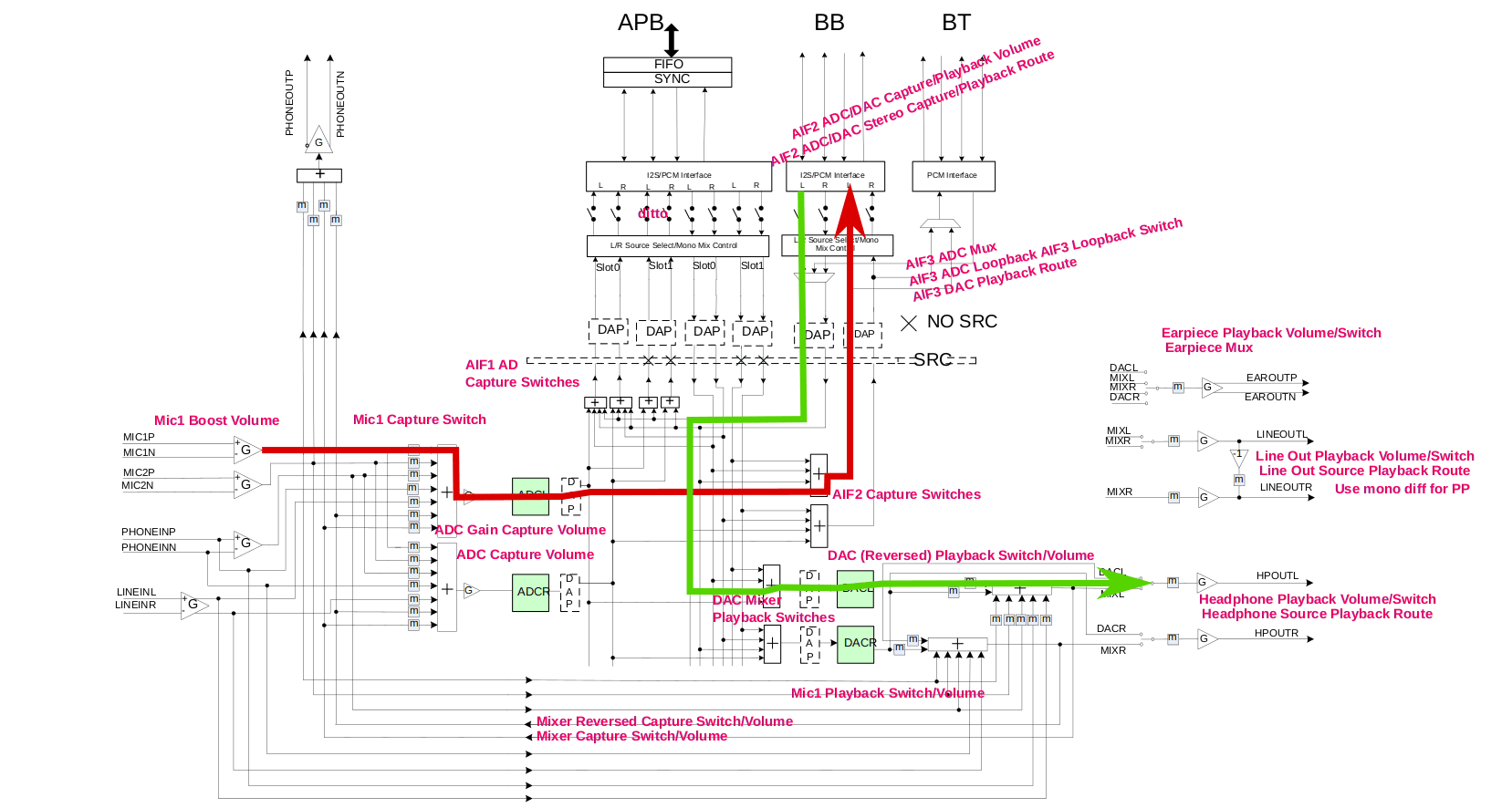
Following this idea, Figure 4 depicts the setup we want to achieve for telephony for the left channel. The red arrow marks the path from the microphone to the modem whereas the green arrow shows the path from the modem to the earpiece/speaker.
|
|
Telephony routes for the left channel
|
Low-level setup
Without going into too much detail, the enablement of any device on ARM platforms is what the BIOS usually does for x86. Meaning - everything is turned off. This step required configuring and activating the Audio PLL, setting up and (un)gateing necessary clocks, bringing the audio codec out of reset state, and configuring the GPIO pins to take and send signals to/from the AIF2 (modem) bus.
Digital audio codec
For the digital part, we want to route the ADC where the microphone is connected to the modem (AIF2 mixer), and the playback from the modem to the DAC where the speaker and the earplugs are connected. For each stage, there exist different mixers that must be configured as well as additional registers to set the data rate, volume, bit width, and audio format. The essential step is to enable ADC (left and right channel) as one source of the AIF2 mixer. There can be more than one source, for example, the AIF2 mixer can also use AIF1 (the Allwinner SoC) as input. For the playback route, we set the source of the DAC mixer to the AIF2 DAC output of the modem. Of course, all parts need to be enabled separately.
Analog audio
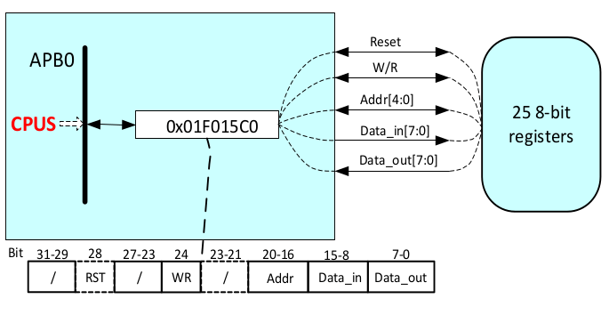
The analog part of the codec is accessed through a single memory-mapped I/O register called AC_PR (Figure 5). Through this register, 32 8-bit data registers can be addressed through the Addr field. In and out data is read/placed by the codec from/into the Data_in and Data_out fields.
|
|
Analog configuration register (Allwinner A64 Manual v1.1, page 362)
|
With the digital part ready, it was time to activate the actual microphone and the earpiece speaker. In Figure 4 all gray boxes marked with an "m" - for mute - can be configured through the ADC mixer. For the microphone, this means that we have to set the microphone as a source of the ADC mixer. Additionally, every device has a configurable amplifier that needs to be enabled. For the microphone, that is the boost amplifier. Since microphones also require a voltage (bias voltage) this must also be configured. And voila, the microphone was working on a test phone call.
For the earpiece, in turn, we needed to configure the DAC mixer as an input source, enable the amp and unmute the device. This worked out of the box and we were able to perform an actual phone call with the PinePhone running Genode.
As a final test, we enabled the speaker for hand-free communication that is connected to the line out. This works analogously to the earpiece, with the exception that the speaker amplifier is external on the PinePhone and needs to be enabled via a dedicated GPIO pin.
So with everything working it's time for a test call using this run script:
Roger Murdock: We have clearance, Clarence.
Captain Oveur: Roger, Roger. What's our vector, Victor?
Tower voice: Tower's radio clearance, over!
Captain Oveur: That's Clarence Oveur. Over.