


Exploring Genode Base HW with Raspberry Pi - further workflow automation
In a previous article I described step by step how to prepare a Raspberry Pi and Genode build system to be able to almost automatically build and test compiled images on a device. There was one piece missing in this puzzle that made it incomplete: after each build device had to be started manually. This article describes my solution to this missing element.
Resetting Raspberry Pi
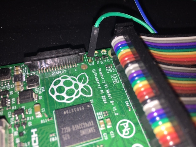
On each Raspberry Pi there is a little hole described as RUN in which a pin can be soldered. Connecting this with one of GND from pins for a moment causes a reset of a device. There are many resources about this in the Internet so I will not write much about it, however one little thing may be important. Many of articles and films say that connecting RUN with with pin placeholder next to it is enough but for some models (at least for Raspberry Pi 3) it doesn't work as this other pin placeholder is used for something else.
Summarizing: to reset Raspberry Pi connect RUN with GND for a moment.
|
|
Location of RUN on Raspberry Pi 1B
|
Relays as electronically controlled switches
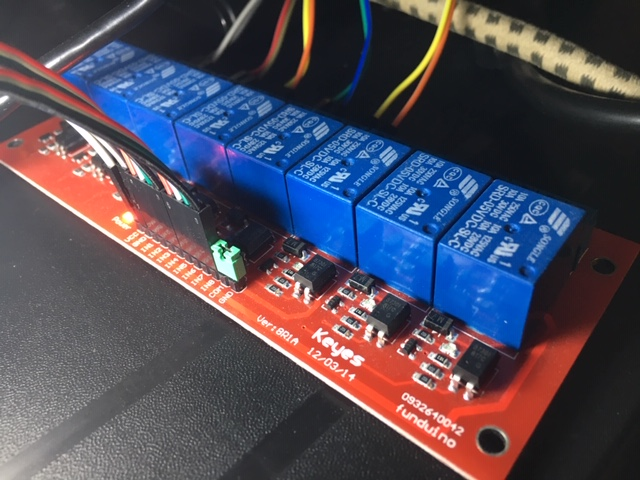
To reset a device after a successful build I needed to be able to make connection of RUN and GND with software from build environment. I have little experience with electronics so to be safe I decided to buy a module with set of relays. Relays completely isolate different electrical circuits from each other - in this case circuit that resets Raspberry Pi and the one that is connected to build system host.
Relays module I bought has 5V coil so it can be powered directly from host's USB and relays are active high (I hope it is a proper terminology in english).
|
|
Relays module used to reset Raspberry Pi
|
Controlling relays
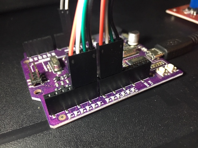
To control relays I use an Arduino Uno (actually a clone). Code for Arduino can be (and typically is) written in C++ but as writing code for Arduino is not my goal (at least not now) I use an existing protocol and implementation called firmata that allows to control GPIO pins remotely from Linux over USB cable (actually it allows for much more but it is what I need).
|
|
Arduino Uno compatible device used to control relays through GPIO
|
Preparing Arduino
Just load Firmata->StandardFirmata from Examples in Arduino environment to the device.
Scripts on the host
Prepare python virtual environment for pyfirmata.
 python3.6 -m venv firmata
 . firmata/bin/activate
 pip install pyfirmata
 deactivate
Python script reset_line.py:
 #!/bin/python3

 import sys
 import pyfirmata
 from time import sleep

 port = "/dev/ttyUSB0"   # device name for connection to Arduino
 board = pyfirmata.Arduino(port)

 it = pyfirmata.util.Iterator(board)
 it.start()

 def resetLine(lineNum):

     pinNumber = lineNum + 4 - 1   # pin number on Arduino
     led = board.get_pin("d:%s:o" % (str(pinNumber)))

     led.write(1)
     sleep(1)
     led.write(0)

 if __name__ == "__main__":
    resetLine(int(sys.argv[1]))
Shell script reset_line.sh just to activate virtual environment and run reset_line.py:
 #!/bin/bash

 cd `dirname $0`

 . firmata/bin/activate

 python3 reset_line.py "$@"
This environment is used by me on Ubuntu 18.04.
Integrating with Genode build system
To be able to use above script from Genode build system I implemented a simple power_on extension to run tool. It's implementation is currently available in commits refernced from Genode issue 3385.
Additionally changes in build.conf are required. Configuration below allows to reset different devices depending on value of BOARD for which build is performed.
 RUN_OPT += --include power_on/command
 RUN_OPT += --power-on-command-cmd /projects/genode/firmata/reset_line.sh
 BOARD_RUN_OPT(rpi2)    += --power-on-command-param 2
 BOARD_RUN_OPT(rpi3_32) += --power-on-command-param 1
Thanks to all goods provided by run tool and with this configuration I'm able to easily test code changes on different devices quite conveniently so it doesn't disrupt my workflow.