


Pine fun - Cutting Linux-driver competencies
The previous episodes of the article series covered the challenges of transplanting complex driver code from the Linux kernel into Genode components. Once running happily in its new habitat, however, the driver code needs a heavy dose of domestication. This article shows how to curb the driver code from the overarching access of power, reset, pin, and clock controls.
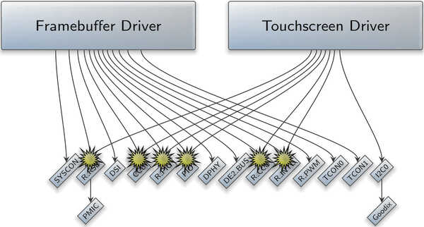
At the end of the previous article, we encountered conflicting hardware access as a hard problem when integrating multiple driver components into one system. It naturally arises on the attempt to combine the framebuffer driver with the touchscreen driver.
|
Each of both drivers assumes the responsibility of managing the clocks, reset lines, pins, and power domains related to the driven devices. As those low-level hardware resources are controlled via system-global hardware-configuration registers, each driver tries to manipulate those central registers. In the concrete scenario, we can observe the following legitimate interplays.
-
Each driver tries to enable an output at the power-management IC (PMIC) that happens to power both the LCD display and the touchscreen controller. The PMIC is accessed via a so-called reduced serial bus (RSB) two-wire bus. Therefore, both components concurrently try to drive the same RSB bus controller.
-
The touchscreen driver modifies the SoC's pin configuration for the four pins connected to the Goodix touchscreen controller, in particular defining one pin as input signal for interrupt delivery, one pin as output signal for reset control, and selecting I2C as pin function for the two I2C wires.
The framebuffer driver modifies the pin configuration to assign PWM as pin function for the brightness control, and defines two pins as outputs for controlling the backlight and LCD reset.
In both cases, the pins are configured via the system-global PIO device.
-
Both drivers interact with the clock and reset control unit (CCU). The touchscreen driver de-asserts the reset signal of the SoC's I2C controller and enables the corresponding bus clock, whereas the framebuffer driver controls the clocks and reset domains of the display engine, MIPI-DSI, DPHY, and the two TCON channels.
There are two principle approaches for the reconciliation of both drivers. One could be tempted to co-locate both drivers into a single component. But this is bad for two reasons. First, it would effectively turn this highly complex component into the central authority over system-management controls, literally yielding power over the whole system, including low-complexity security-sensitive Genode components unrelated to the drivers. Second, with each driver added, this component would grow bigger. Down the line, we would ultimately end up with an all-powerful monolithic driver subsystem that stands in the way of a clean separation of concerns. E.g., in contrast to an individual framebuffer driver that can be started, removed, and restarted on demand, a monolithic driver component that includes drivers for persistent storage couldn't be restarted without risking data loss.
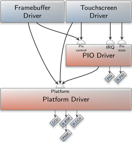
The right way to go is the consequent removal of low-level system-control access from the drivers. In Genode, the natural place for clock and power management functionality is the platform driver we introduced in the earlier article One Platform driver to rule them all, whereas the pin-MUX configuration and GPIO access are covered by the dedicated PIO driver component. The following illustration shows the aspired architecture.
|
The framebuffer and touchscreen drivers no longer access the low-level system-control registers directly. Instead, the platform driver controls the reset, clock, and power states depending on the presence of its clients. Analogously, the driver's direct GPIO access of the direct pin-MUX manipulation is replaced by the use of the services provided by the PIO driver component.
SoC-aware platform driver
The picture above calls for the enhancement of the platform driver with SoC-specific driver code for controlling clocks, power, and reset lines. Instead of laying those controls into the hands of the driver, the platform driver implicitly drives them based on the mere presence of a related platform client. For example, the following policy assigns the "tcon0" device to the client labeled as the framebuffer driver.
 <policy label="fb_drv -> " info="yes">
     ...
     <device name="tcon0"/>
     ...
 </policy>
The "tcon0" device is declared as follows. Note the declaration of the <clock>, <power-domain>, and <reset-domain> sub nodes. The names of listed resets, clocks, and power outputs are defined by the implementation of the SoC-aware platform driver.
 <device name="tcon0" type="allwinner,sun8i-a83t-tcon-lcd">
     <io_mem address="0x01c0c000" size="0x1000"/>
     <irq number="118"/>
     <reset-domain name="tcon0"/>
     <reset-domain name="lvds"/>
     <power-domain name="pmic-gpio0"/>
     <clock name="bus-tcon0" driver_name="ahb"/>
     <clock name="tcon0"     driver_name="tcon-ch0"/>
     <clock name="dummy"     driver_name="tcon-pixel-clock"/>
 </device>
Given this information, the platform driver knows that the framebuffer driver depends on the reset lines "tcon0" and "lvds" being de-asserted. It also knows that the driver requires the powering of the "pmic-gpio0" output of the PMIC chip. It also knows that the clocks "ahb", "tcon-ch0", and "tcon-pixel-clock" must be set up. Once the framebuffer driver connects to the platform driver, the platform driver can establish all those requirements implicitly while establishing the connection. This not only relieves the actual driver from those low-level peculiarities. It also enforces the proper reset of these settings whenever a driver disappears - with no active participation of the driver needed. For reference, the implementation of the A64-specific platform driver can be found at the following link.
- SoC-aware platform driver for the Allwinner A64 SoC
-
https://github.com/genodelabs/genode-allwinner/tree/master/src/drivers/platform/a64.
To simplify the implementation of the clock, reset, and power drivers within the SoC-specific platform driver, the generic platform driver offers a few handy utilities in the form of the clock.h, reset.h, and power.h headers. In practice, most system-control operations come down so toggling a single bit for (de-)asserting a reset line, or for (un-)gating a clock.
Curbing the Linux driver code
The SoC-specific platform driver looks fairly simple. However, at the client side - in the Linux driver component - two hairy questions arise.
-
How to remove the direct access of the low-level system-control registers while keeping the Linux code happy? Some the related Linux subsystems, in particular those related to pin-MUX configuration, are quite central to the healthy operation of the Linux kernel. They are mandatory and cannot be ripped out.
-
Which clocks, resets, power domains are actually expected by the driver? Candidates are plenty. The answer seems rather vague and is scattered over many kernel modules.
Mimicking Linux subsystems
We encounter the first problem when trying to remove the drivers/pinctrl/sunxi/* driver code, which interacts with the PIO device. The Linux code briefly complains and just stops.
mv64xxx_i2c 1c2ac00.i2c: can't get pinctrl, bus recovery not supported
To lift the clouds a bit, it helps to enable the debug messages in Linux drivers/base/dd.c and drivers/base/core.c by placing the following line at the top of those files.
#define DEBUG
This results in a very plausible message.
 i2c 0-005d: probe deferral - supplier 1c20800.pinctrl not ready
 i2c 0-005d: Added to deferred list
The I2C subsystem depends on the pinctrl driver, which we just removed. To satisfy this dependency without using the actual pinctrl driver, we have to create a custom kernel module that looks like the original pinctrl but is just an almost empty hull. To create such a stub driver, the easiest way is to start looking at the original driver code and mirroring its basic structure. The original driver code can be found by inspecting the device tree, which contains the following node.
  pio: pinctrl@1c20800 {
   compatible = "allwinner,sun50i-a64-pinctrl";
By searching for the compatible string inside the drivers/pinctrl/sunxi directory, we find the right spot.
 src/linux$ grep "allwinner,sun50i-a64-pinctrl" drivers/pinctrl/sunxi/*
 drivers/pinctrl/sunxi/pinctrl-sun50i-a64.c:  { .compatible = "allwinner,sun50i-a64-pinctrl", },
To mirror the driver's structure, it is good to start looking at the "allwinner,sun50i-a64-pinctrl" string and follow its tracks. It appears inside a table of of_device_id entries.
 static const struct of_device_id a64_pinctrl_match[] = {
   { .compatible = "allwinner,sun50i-a64-pinctrl", },
   {}
 };
The table a64_pinctrl_match is referenced by a struct called a64_pinctrl_driver.
 static struct platform_driver a64_pinctrl_driver = {
   .probe  = a64_pinctrl_probe,
   .driver = {
     .name   = "sun50i-a64-pinctrl",
     .of_match_table = a64_pinctrl_match,
   },
 };
 builtin_platform_driver(a64_pinctrl_driver);
The struct refers to a probe function a64_pinctrl_probe.
The implementation is merely a wrapper around sunxi_pinctrl_init.
 static int a64_pinctrl_probe(struct platform_device *pdev)
 {
   return sunxi_pinctrl_init(pdev,
           &a64_pinctrl_data);
 }
Piece by piece, we assemble a custom puzzle of (almost) empty functions and structures. By using the exact same symbol names as the original driver, our stub driver nicely overtakes its position, in particular our initcall is called at the appropriate time.
Fast forward, the complete stub driver for replacing the pinctrl driver can be found at src/lib/lx_emul/a64/pio.c. It is arguably not trivial, which is due to the fact that the touchscreen driver uses one GPIO pin as interrupt source. Hence, our stub needs to mimick an interrupt controller as well. The interaction with Genode's PIO driver is done via calls to the lx_emul_pin_* API.
The clue for sneaking our stub driver into Linux as GPIO driver is the function gpiochip_add_data, which takes a gpio_chip struct as argument. This struct defines a number callbacks that our stub driver provides for interacting with the pins. The following two callbacks are especially interesting.
- of_xlate
-
is called with the coordinates of a GPIO pin as arguments and returns a pin number. The organization of the namespace for such pin numbers is up to us. As the PIO pins of the A64 SoC are organized in a number of banks with 32 pins per bank, a suitable naming scheme is
number = bank*PINS_PER_BANK + pin_within_bank
- set
-
sets an output pin of a given number (according the result of of_xlate) to the specified level. This function triggers the physical effect.
Compared to the removal of the pinctrl subsystem, replacing the reset (drivers/reset/*) and clock (drivers/clk/*) controls is relatively simple. For stubbing the clock control, there already exists a reusable stub driver within the repos/dde_linux repository at lx_emul/shadow/drivers/clk/.
Gathering the required clock, reset, and power controls
The second tricky question is to find out the few needles in the haystack of clock, reset, and power controls that are required by the individual driver. There may be more than a dozen of such prerequisites. When missing merely one, the driver won't work.
Of course, the device tree is always a nice reference to start with. Specifically the clocks and reset properties of the device tree provide useful clues. For example, the device node for the tcon1 contains the following declarations.
 tcon1: lcd-controller@1c0d000 {
   ...
   clocks = <&ccu 48>, <&ccu 101>;
   clock-names = "ahb", "tcon-ch1";
   resets = <&ccu 25>;
   reset-names = "lcd";
   ...
The numbers can be correlated in definitions found at include/dt-bindings/clock/sun50i-a64-ccu.h in the Linux source tree.
 ...
 #define CLK_BUS_TCON1 48
 ...
Those definitions, in turn, show up in the driver's source tree - in this particular case drivers/clk/sunxi-ng/ccu-sun50i-a64.c - which draws the connection to the physical coordinates of the clock.
 ...
 static SUNXI_CCU_GATE(bus_tcon1_clk,  "bus-tcon1",  "ahb1",
                       0x064, BIT(4), 0);
 ...
 static struct clk_hw_onecell_data sun50i_a64_hw_clks = {
   .hws  = {
     ...
     [CLK_BUS_TCON1]   = &bus_tcon1_clk.common.hw,
     ...
Now, a look into the CCU documentation for the 4th bit of the register 0x64 should close the circle, prompting us to add an appropriately named clock definition Genode's platform driver.
I/O register tracing
That said, unfortunately it is all too easy to miss one piece of the puzzle when merely looking from above (from the device tree). In this case, a look from below may help to complete the picture: To find the right bits - and also to quickly rule out the wrong ones - the low-level tracing of register accesses is sometimes inevitable.
Usually, Linux subsystems come with their own pieces of infrastructure, which provide us with a convenient hook for instrumentation. For example, all parts of the driver for the Allwinner clock and reset unit (CCU) happen to include the file linux/drivers/clk/sunxi-ng/ccu_common.h. Hence, changes of this file affect only the driver code we are interested in. So we can add the following hillbilly I/O tracing facility that captures all writel and readl operations.
 static inline void my_writel(u32 value, volatile void __iomem *addr)
 {
   printk("::: writel 0x%x addr=0x%p\n", value, addr);
   writel(value, addr);
 }
 #undef writel
 #define writel my_writel

 static inline u32 my_readl(volatile void __iomem *addr)
 {
   u32 result = readl(addr);
   printk("::: readl addr=0x%p -> 0x%x\n", addr, result);
   return result;
 }
 #undef readl
 #define readl my_readl
The ":::" prefix is just a band aid to easily distinguish the trace output from regular log output. Note that the instrumentation print virtual addresses though. To correlate those virtual addresses with physical addresses, we can add an instrumentation to the lx_emul_io_mem_map function in lx_emul/io_mem.cc.
 log("mapped memory-mapped I/O resource ", Hex(phys_addr),
     " (size=", Hex(size), ") to ", ret);
This I/O tracing approach is extremely simple, yet surprisingly powerful. Consider the following ideas.
-
One can programmatically filter out superfluous noise by making the printk statements conditional. For example, skipping the output for certain uninteresting accesses (like polling a certain bit), or keeping a counter and starting the output not before the counter has reached a certain value.
-
Even more interesting is the conditional skipping of write operations to confirm that certain register accesses are really needed. One can even change the bits written to the hardware registers to see, e.g., the effect of different clock settings.
-
As a sledgehammer approach, one can replay a once gathered register trace at the startup of Genode's platform driver and skip as many writel operations in the driver as possible.
By iteratively tweaking the filtering, thousands of register accesses during the initialization of the touchscreen driver could be condensed to the following few interesting accesses. With the focus drawn to such a few registers, the manual review of the bits suddenly becomes practical.
 writel 0x5514     addr=0x2008   PLL_AUDIO control register
 writel 0x515      addr=0x2040   PLL_MIPI Control Register
 writel 0x90001031 addr=0x2000   PLL_CPUX Control Register
 writel 0x90002d00 addr=0x204c   PLL_DDR1 Control Register
 writel 0x90041811 addr=0x2028   PLL_PERIPH0 Control Register
 writel 0x81000002 addr=0x215c   MBUS Clock Register
 writel 0x10001    addr=0x206c   Bus Clock Gating Register 3
That said, keep in mind that we can never be sure to capture all I/O accesses this way. Drivers may operate in a way that bypass the readl and writel functions. Also, the place of the instrumentation is important. For example, if a driver accesses registers indirectly using the drivers/base/regmap/ utilities, one needs to the place the instrumentation inside the regmap implementation.
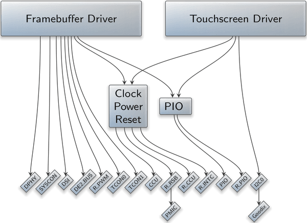
The drivers reconciled
The result of the described development step is best illustrated by the configuration of the drivers subsystem for Genode's interactive system scenarios on the PinePhone. It clearly documents the enforced relationship between the drivers and the related hardware at an almost intuitive level of abstraction. For example, it becomes perfectly clear, which driver has the authority over which GPIO pin. The access to low-level system-management registers is exclusively guarded by the platform driver. Isn't it beautiful?
|