


"U can't touch this"
With our on-going effort to add more and more Genode support for NXP's i.MX 8M Quad EVK SoC, which is for example deployed by the Librem 5 smartphone from Purism, it became time to add touchscreen input to the list of Genode supported features, because a phone without a touchscreen would not be of much use, would it be?
For this purpose we ordered NXP's MX8_DSI_OLED1 display development kit. It can be found as an accessory on the NXP website. The kit features an OLED display and a Synaptics RMI4 compliant touch panel. As one should know a touchscreen device consists of two separate devices. First, the touch panel and second, the display panel that require different drivers.
|
|
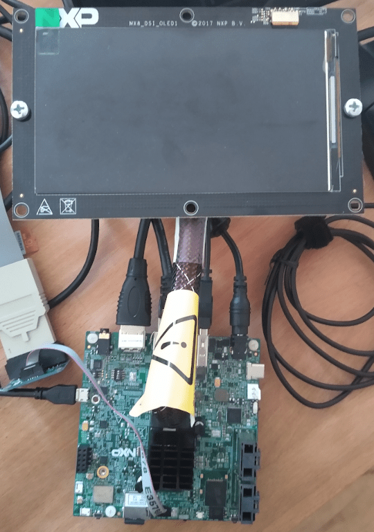
OLED1 panel connected to i.MX8
|
Linux test drive
As first step with new hardware we always perform a test on native Linux. For this purpose we build NXP's vendor kernel (branch 4.14-2.0.x-imx), connected our OLED and saw a nice flickering display. These kind of things can occur and are not as unusual as it sounds. We found a solution at the NXP forum of someone who had the same issue with the OLED1 display, and therefore, could produce a correct output by merely changing some display-timing parameters. As it turned out, not all OLED1 displays seem to omit the same behavior as another one we ordered later on worked perfectly fine with the stock vendor kernel. This might be caused by a different revision of the display or an alternate display firmware.
Speaking of revisions: In the ARM SoC world there most likely exist several revisions of a SoC. For example, the i.MX 8M Quad ships revisions A0, A1, B1, B2, B3, and B4 (Section 1.3) and we own boards with revision A1 and B3 at Genode Labs. Different revisions have slightly different characteristics. In our case, this meant that the touch panel is connected to a different pin with the SoC for revisions A1 and B3, leading to different I2C controllers being used. Therefore, one has to make sure to load the correct device tree during Linux boot up in order to flawlessly drive the touch panel. With everything working as planned we started the enablement of the display on Genode.
Porting the OLED display driver
In Genode release 20.02 we had enabled basic Display Controller Subsystem (DCSS) with HDMI support for the i.MX8 platform which consists of the native Linux driver ported to Genode's dde_linux environment. As the name "MX8_DSI_OLED1" suggests our display is not connected via HDMI to the SoC but through MIPI DSI which stands for Display Serial Interface, while the MIPI Alliance is a business standardization body. DSI is a standardized connection that is used, for example, in most smartphones, smart watches, and embedded displays today.
Okay, that means we had to extent our i.MX8 display driver with support for DSI. Therefore, we ported the DSI physical layer, the DSI bridge (Northwest Logic), and support for the OLED display to Genode. While doing so we noticed, that the driver or drivers required access to i.MX8 I/O multiplexer, the system reset controller, power domains, and low system clocks/PLLs which is not unusual for a vendor kernel and is one reason many of these kind of drivers will never make it into the upstream Linux kernel because things like the I/O multiplexer should never be touched directly by a driver. On Genode we do not allow this kind of hardware accesses by a driver as well and often rely on the boot loader (i.e. U-Boot) to perform the necessary low level platform initialization.
Unfortunately, unlike HDMI, there exists no initialization code within U-Boot for the DSI case and we had to implement the I/O multiplexer (IOMUX), power domain, and clock initialization in Genode's platform and bootstrap components on base-hw. For the IOMUX and the power domain we traced the necessary values in Linux and applied them during Genode startup. In the platform driver we enabled the necessary clocks which consists of setting a reference input clock and a clock divider in order to configure the desired clock rate as determined by the Linux driver. One of these reference clocks is the Video1 PLL of the i.MX8 SoC which caused some trouble as we will discuss next.
PLL programming on i.MX8
Simply speaking, a phase locked loop (PLL) is used to transform a low input frequency into a high harmonic output frequency. For our scenario, we wanted to program the Video1 PLL to output 1200 MHz and use it as a reference clock for the pixel clock. The pixel clock in turn would set a divider of 10 to achieve a 120 MHz frequency which is required for a Full-HD display in order to achieve about 60 Fps.
To reach our 1200 MHz PLL frequency goal, we set the input oscillator of the PLL to 25 MHz and through a rather complicated formula determined that the output divider had to be 2 and the frequency divider (which actually is a multiplier) had to be 60. We setup these values and examined that our display remained as black as it was before. We inspected the Linux kernel and found that there is some kind of protocol in place on how to program a PLL. After writing new divider values, the "new divider value" bit has to be set by software and the software then has to wait until the hardware sets the "new divider value handshake" bit, and thus, asserts that the PLL's frequency is now stable. We did just that and it changed ... nothing. Further investigation showed that Linux accessed two more bits nameley: PD and CLKE. The documentation remains a little vague on these two:
 CLKE: PLL output clock clock gating enable active high
 PD  : PLL output clock clock gating enable active high
Aha. We found that PD must mean "power down" and has to be set to 0 in order to power-on the PLL. Indirectly, Linux also programs CLKE, which actually does what the documentation says: It enables clock gating. If CLKE is not enabled, all accesses to any clocks that depend on this PLL and all hardware that in turn depends on these clocks will not return (literally - with no hardware exception being triggered) implying they receive no input signal (are ungated in clock module lingo). So, we have to set: PD = 0 and CLKE = 1.
And voila, our driver was working and the display presented a correct picture. There was only one disturbing thing to be observed: the picture update rate was about 1s per frame and we could see the picture slowly drawing its way from top to bottom.
Something had still slipped our attention and it turned out to be:
BYPASS: PLL bypass control active high
After some more i.MX8 manual studies, we found that the BYPASS bit was set and simply routed the input signal to the output of the PLL, which in our case meant the input of our pixel clock would be 25 MHz instead of 1200 MHz and that would additionally be divided by 10 within the pixel clock. 2.5 MHz are not exactly the 120 MHz we aimed for but at least it explained the low display update rate. So let's just disable the BYPASS and everything should be fine, said no one, because the screen became dark as the night again. Btw. the nice thing about OLED displays is that they don't have a backlight, so there is no way to check if they are even powered on.
As one can imagine we double and triple checked all our clocks and initialization values, but the most reliable way to verify that the hardware is in the state one expects is to use other hardware. Enter JTAG debugger ...
JTAG Debugging
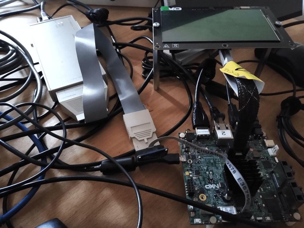
For the purpose of debugging hardware we use a Lauterbach - Power Debug Interface.
|
|
From left to right to front: Power Debug, NXP OLED1 panel, i.MX 8M Quad
|
The debugger is connected via JTAG to the SoC and via USB to a Linux host. With the host software it is possible to examine RAM, device memory, CPU register, page tables, clocks, clock gating, etc. - all in a human readable form.
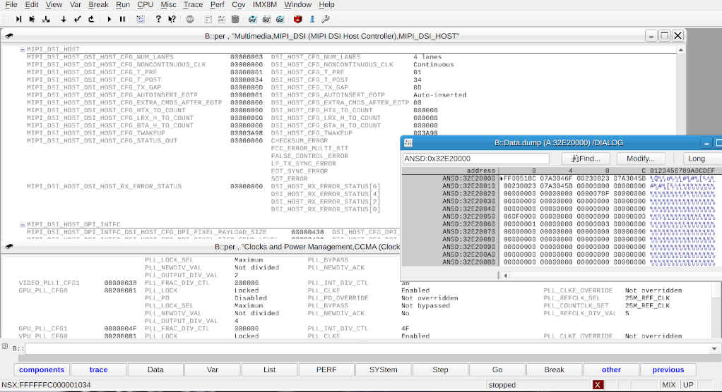
For our purpose we inspected all devices (MIPI, CCM, DCSS, I/O MUX, SRC) that are required by the display driver. An example output can be seen below:
|
|
Trace32 dump of MIPI DSI.
|
This way we were able to verify that the values that we had written in the driver were actually the same as seen by the hardware, because in the past we had many issues with ARM and caches, where values accidentally ended up in caches. Everything looked good.
The debugger also allows to dump arbitrary memory regions into different file formats. We used this feature to dump the memory regions from the devices of interest of both Linux and Genode after the display was initialized. Funnily enough, all values but DMA values turned out to be the very the same for Genode as for Linux. This means, our driver programmed the OLED correctly.
So, what could be the reason for our driver not working? There were only two possible explanations left: Either timing, which means Genode was doing something too slow or too fast during device initialization or some intermediate device interaction we did not notice with one of the devices involved or one not inspected by us.
The VMM trick
A clean way to inspect all device interactions issued by the Linux kernel would be to put the Linux kernel into a virtual machine monitor and log all accesses to the devices we want to examine from there. Fortunately, Genode recently added support for ARMv8 into its custom VMM on base_hw. The VMM also allows for direct device pass-through as demonstrated in our Android VM line of work. To be able to log device accesses from the VMM we added a device model that does not directly pass the device to the VM, but works on a trap/execute model. So, if Linux writes or reads to/from a device, it traps into the VMM. The VMM in turn retrieves the correct device by it's guest physical fault address, traces the device access, and executes the access on behalf of Linux. In order to lower the "noise" these traces produce we created a stripped down minimal device tree that only contains essential devices (like the CPUs) and devices required by our MIPI DSI controller setup. To our relief this approach actually worked, Linux was able to initialize the display successfully and we were able to produce a trace as shown in the snippet below for the MIPI DSI bridge.
 ...
00000630: 00000001 30a0032c 00000000 00000000  ....,..0........
00000640: 00000001 30a0031c 00000000 00000000  .......0........
00000650: 00000000 30a00330 00000001 00000000  ....0..0........
00000660: 00000001 30a00300 00000000 00000000  .......0........
00000670: 00000001 30a002a8 ffffffff 00000000  .......0........
 ...
Column 2 displays a read (0) or write (1) operation, column 3 is the device address, and column 4 for the actual value. The initial trace contained ~5000 device accesses. What to do with the trace then? We simple dumped it into our base-hw bootstrap component, which runs with the MMU turned off and executed it. The result did not vary and still produced a black OLED display. While playing around with the trace we accidentally also started our ported driver after the trace and to our great surprise the display started working and produced flawless pictures. What, are you kidding me? Okay, next we tried to figure out what instructions of the trace were relevant in order for our driver to function. So we eliminated all reads from the trace first. Still working, good. Next we made all clock accesses read only, implying that Linux could not program any clocks and Genode's configuration had to be used. Also working, which means we did the clock and PLL initialization correctly. After many iterations we brought the trace down to about 40 values bootstrap had to write upon startup. These concerned the display parameters in DCSS, the enablement of the MIPI PHY, and the initial MIPI DSI bridge setup and were all static values issued by our ported driver as well. Why this was necessary remained unclear, maybe our driver performed the actions in a different order.
Because we ran out of time and all we wanted was a working framebuffer without all the bells and whistles "modern" hardware (like on the fly compression, HDR, pixel format conversion, etc. ... but no double buffering, though) offers, we moved the trace into the startup code of our driver and finally had a working OLED display. After all our initial intention was to write a touch panel driver, right?
U can't touch this
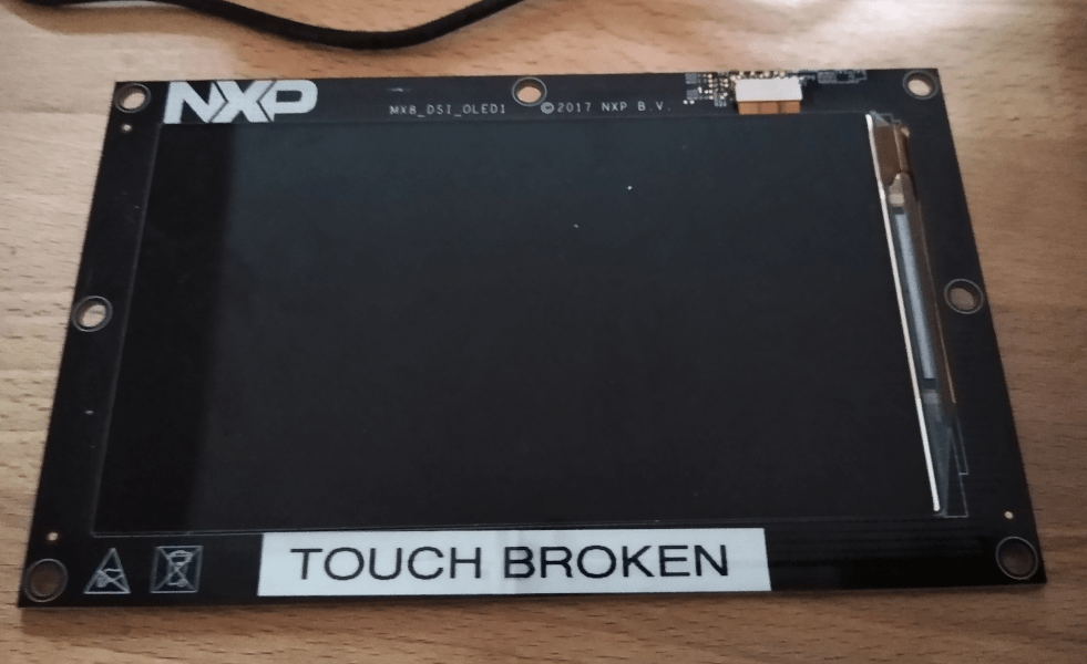
Since we are cautious, we booted a native Linux again in order to verify that the touch panel driver was still working correctly. Well, it wasn't. Nothing. Zero. We double checked everything again (board revision, device tree, kernel driver) and found that that the device was initialized successfully by Linux, but there occurred no interrupts when one actually touched the display. What had changed, because in the beginning the touch input had worked correctly? Maybe all our testing and debugging, with flashes, flickers, and hot resets occurring broke something. We gave up, send the display to the eternal storage (cupboard), and ordered a new one.
|
|
"Another one bites the dust"
|
Fortunately, the touch panel worked out of the box on the freshly delivered display and we are still happy that shipment only took two days from Texas to Dresden.
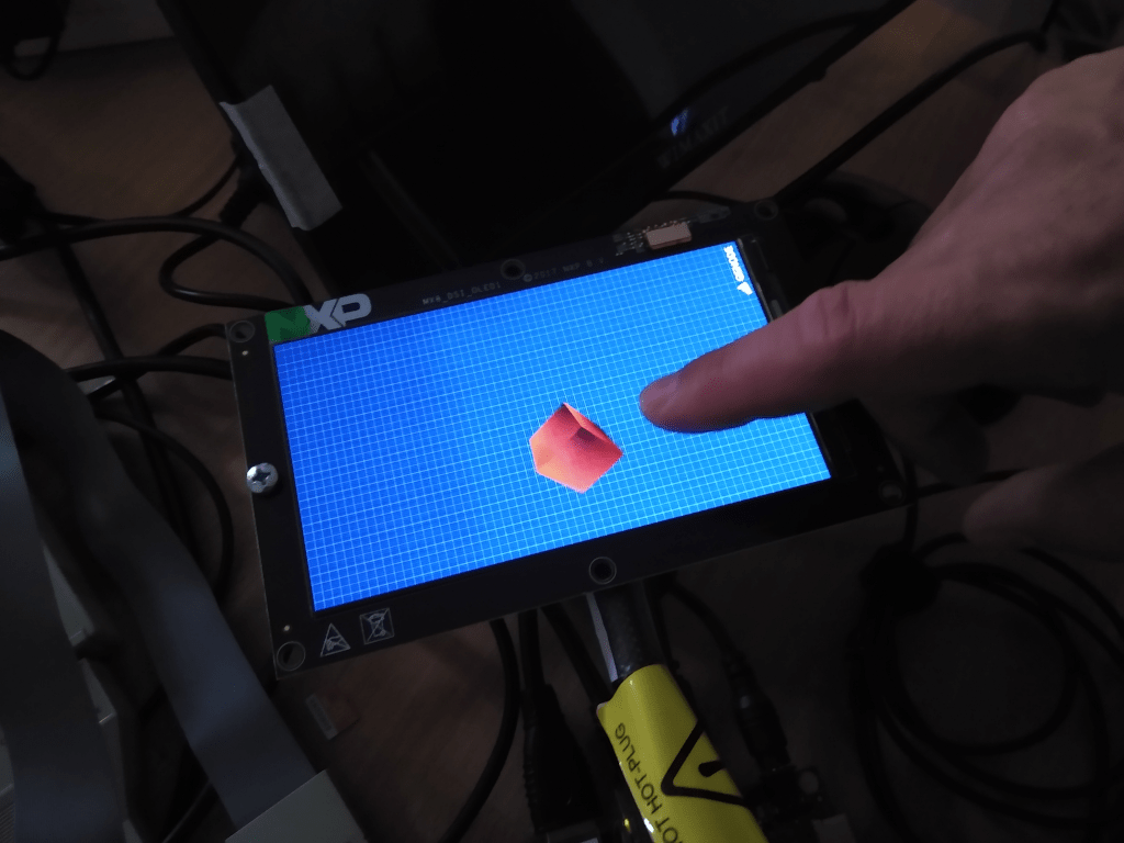
All in all the touch panel turned out to be way less complicated than, for example, a display driver. The communication to and from the touch panel is realised through an I2C bus where data can be send and received from. Upon a touch event the panel asserts a GPIO pin interrupt that has to be delivered to the driver where the touch data for up to 10 fingers is retrieved. The retrieved data in turn is send to Genode's event session interface and we were able to realise the driver as a native Genode component in less than 300 lines of code - including the I2C parts. As a simple demonstration we started Genode's nano3d test featuring touch input and our ported i.MX8 OLED driver.
|
|
"Just touch it!"
|
Lessons learned
Never underestimate the complexity of display subsystems. For the i.MX8 framebuffer driver over 60.000 lines of Linux code are necessary compared to 300 native lines of code for touch input. These systems have become unnecessarily complex with little documentation and features we don't need or want to take advantage of.
When porting such drivers it is a good idea to build a minimal Linux with as little hardware access as possible in order to determine the actual working set of a driver. Also vendor kernels often seem to break basic Linux coding guidelines and take unclean shortcuts to save development costs making them unfit for upstream Linux kernels and hard to port. Unfortunately, these kind of drivers are often the only reference implementation available at all and are used by everyone. The general assumptions sounds like: If it runs on Linux it will in turn run on Android and that is good enough - leaving everyone else out of the picture.
In the future we will more often take advantage of the VMM tracing approach, because this way we can consistently inspect the driver/hardware interaction.
Notes
-
We have uploaded a YouTube video showcasing i.MX8 demonstrations including touch on Genode. By the way, i.MX 8M is not a "home-made circuit board" as some watcher suggests
-
The second OLED display we ordered did not require the aforementioned Linux trace
Cheers